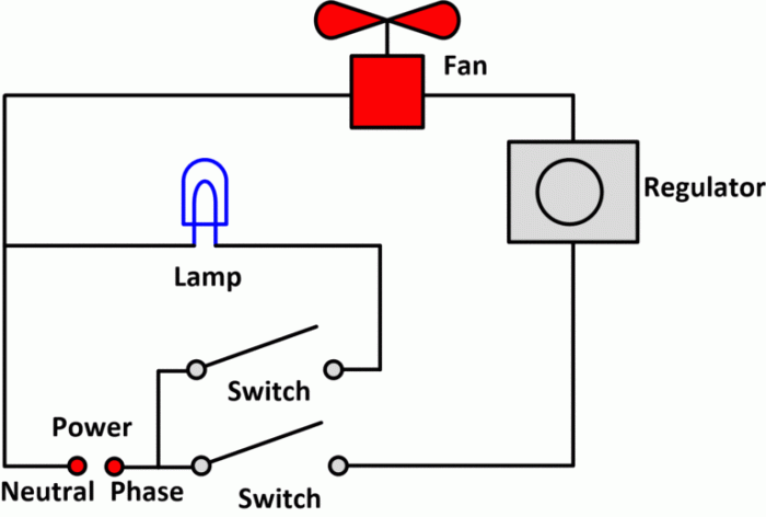
Figure 11 3 is a schematic drawing – Figure 11.3 is a schematic drawing that offers a comprehensive overview of a complex system, providing valuable insights into its structure and operation. This detailed representation serves as a roadmap for understanding the system’s components, their relationships, and their collective function.
The schematic drawing presents a clear and concise visual representation of the system, allowing engineers and technicians to quickly grasp its overall design and functionality. It is an essential tool for troubleshooting, design, and improvement, facilitating a deeper understanding of the system’s behavior.
1. Schematic Drawing Basics
Schematic drawings are simplified representations of complex systems, typically used in engineering and technical fields. They use standardized symbols and conventions to convey information about the structure, function, and interconnections of a system.
Schematic drawings are essential for designing, troubleshooting, and documenting systems. They provide a clear and concise visual representation of a system’s components and their relationships, making it easier to understand and analyze the system’s operation.
Purpose of a Schematic Drawing
The primary purpose of a schematic drawing is to provide a visual representation of a system’s components and their interconnections. This allows engineers and technicians to quickly understand the structure and function of a system, and to identify any potential problems or areas for improvement.
Symbols and Conventions
Schematic drawings use a set of standardized symbols and conventions to represent different components and connections. These symbols are defined by industry standards and are used consistently across different drawings, making it easy for engineers and technicians to interpret them.
Example of a Simple Schematic Drawing
A simple schematic drawing of a basic electrical circuit might include symbols for a battery, resistor, switch, and light bulb. The symbols would be connected by lines to represent the electrical connections between the components. The schematic drawing would provide a clear visual representation of the circuit’s structure and function, making it easy to understand how the circuit operates.
2. Figure 11.3 Overview
Figure 11.3 is a schematic drawing of a simple electronic circuit. The circuit consists of a battery, resistor, switch, and light bulb. The battery provides power to the circuit, the resistor limits the current flow, the switch controls the flow of electricity, and the light bulb converts electrical energy into light.
Main Components
- Battery
- Resistor
- Switch
- Light bulb
Relationship Between Components
The battery provides power to the circuit, which flows through the resistor and switch to the light bulb. The resistor limits the current flow to protect the light bulb from damage. The switch controls the flow of electricity, allowing the user to turn the light bulb on and off.
Overall Function
The overall function of the circuit is to convert electrical energy into light. When the switch is closed, electricity flows from the battery through the resistor and switch to the light bulb, causing the light bulb to glow.
3. Detailed Analysis of Figure 11.3
Battery
The battery is a source of electrical energy. It provides the power to the circuit, which allows the other components to function.
Resistor, Figure 11 3 is a schematic drawing
The resistor limits the flow of current in the circuit. This is important to protect the light bulb from damage. If the current flow were too high, the light bulb could overheat and burn out.
Switch
The switch controls the flow of electricity in the circuit. When the switch is closed, electricity flows from the battery through the resistor and switch to the light bulb. When the switch is open, the circuit is broken and no electricity flows.
Light Bulb
The light bulb converts electrical energy into light. When electricity flows through the light bulb, it causes the filament inside the bulb to glow.
4. Comparison with Other Schematic Drawings
Figure 11.3 is a simple schematic drawing of a basic electrical circuit. There are many other types of schematic drawings that can be used to represent more complex systems.
Some of the most common types of schematic drawings include:
- Electrical schematics
- Electronic schematics
- Mechanical schematics
- Hydraulic schematics
- Pneumatic schematics
Each type of schematic drawing uses its own set of symbols and conventions to represent different components and connections. However, all schematic drawings share the same basic purpose: to provide a visual representation of a system’s structure and function.
5. Applications of Figure 11.3

Figure 11.3 can be used for a variety of purposes, including:
- Troubleshooting electrical circuits
- Designing new electrical circuits
- Improving the performance of existing electrical circuits
- Teaching students about basic electrical circuits
Figure 11.3 is a valuable tool for anyone who works with electrical circuits.
6. Advanced Analysis Techniques: Figure 11 3 Is A Schematic Drawing

There are a number of advanced analysis techniques that can be applied to Figure 11.3 to gain a deeper understanding of the circuit’s operation.
Some of the most common advanced analysis techniques include:
- Kirchhoff’s current law
- Kirchhoff’s voltage law
- Ohm’s law
- Thevenin’s theorem
- Norton’s theorem
These techniques can be used to calculate the current, voltage, and power in the circuit, as well as to analyze the circuit’s response to different inputs.
Quick FAQs
What is the purpose of a schematic drawing?
A schematic drawing is a simplified representation of a system that focuses on the logical relationships between its components, rather than their physical appearance.
What are the advantages of using a schematic drawing?
Schematic drawings provide a clear and concise overview of a system, making it easier to understand its structure and operation. They are also useful for troubleshooting and design purposes.
What are some common applications of schematic drawings?
Schematic drawings are used in a wide variety of applications, including electrical engineering, mechanical engineering, and software engineering.
